
Stanford Center on Longevity: Design Challenge (Senior Design)
Challenge Goals:
- Create well-designed, practical solutions that address key issues associated with aging
- Encourage a new generation of students to become knowledgeable about aging issues
- Provide promising designers with a path to drive change in the world
Challenge Overview
Background
Designers and technologists are waking up to aging societies as a major trend of our century, but they most often view aging as what happens to someone else. In our rush to fix problems, we are ignoring possibilities that could lead to greater happiness for individuals in later life. We need to understand the goals and dreams of older individuals from their perspective and create solutions that help them live the best life possible.
Design Track Categories
The challenge will consist of three tracks: Mind, Mobility, and Financial Security, reflecting the Center’s belief that people thrive best when they are mentally sharp, physically fit, and financially secure throughout their entire lives. Each of these tracks will have its own expert judges, award up to $17,000 in total cash prizes, and offer sponsored travel to Stanford, where finalists will present their designs to prominent industry, academic, and government leaders.
Challenge Track Descriptions
Mind Challenge: “Delight the Mind”
The 2015-2016 Challenge focuses on solutions that improve psychological functioning by encouraging lifestyles and practices that people want to do. Exercising your brain through activities that delight, for example, or encouraging easy-to-adopt lifestyles and fun practices that:
- Improve cognitive performance
- Enhance emotional wellbeing
- Foster civic engagement
Mobility Challenge: “Discover the Motion”
Remaining active physically creates a multitude of benefits: reduction in chronic disease, protection against heart disease and depression, and enabling independence. It is increasingly apparent that even relatively moderate amounts of activity provide significant benefits. The goal of this challenge is to build activity into life by making activities fun.
Examples of the kinds of solutions we envision include:
- Encourage movement through intergenerational activities
- Encourage physical activities by doing for others
- Create devices that encourage “micro-activities” during normal daily life
- Build fun games that encourage movement
- Use sustainability goals to motivate activity
Financial Security Challenge: “Foster Financial Fitness”
Happiness comes in large part from financial security — but it’s often difficult for the young and even middle aged to start and stick with lifetime fiscal plans. This challenge looks for ways to make this planning easier, less stressful, and more successful.
Solutions to this challenge could include:
- Invent ways to get younger people to create a lifetime financial plan
- Gamification
- Models that create milestones at different life points
- Find ways to create continual awareness of how financially fit you are - is there a “Financial Fitbit”?
- Build tools for envisioning financial outcomes based on current decisions
- Find ways to encourage intergenerational conversations about money
Group Members: David Chon, Ben Morag, Jesusxavier Diaz
Problem Statement
The first plan of action was to do some background research on the Problem Statement.
Stanford Center on Longevity, 2016 Design Challenge:
“Using Happiness to Optimize Longevity”
“…we are ignoring possibilities that could lead to greater happiness for individuals in later life. We need to understand the goals and dreams of older individuals from their perspective and create solutions that help them live the best life possible.” [1]
Background
As people age numerous physical problems surface. The main reason the elderly get hurt is due to falling. There are many reasons why the elderly fall in the first place; including dizziness, insufficient muscle strength, coordination, and even slow reflexes. However, the main cause of falling amongst the elderly is knee problems. After surveying a few elderly people at a local senior community, most of them claimed to have pain in their knees due to old age and knee injuries. Most injuries can affect any of the ligaments, bursa, or tendons surrounding the knee joint. Diseases or conditions that involve the knee joint can cause pain within the knee. Many of the symptoms of knee pain can be a result of excess fluid forming in the joint.
The knee joint is a modified hinge joint and has six degrees of freedom. The movements of the knee joint are described in different motions: flexion, extension, medial rotation and lateral rotation. Flexion is the motion to bend the knee and extension is exactly the opposite, the extension of the knee. There are two groups of muscles located at the knee. The front of the thigh contains four quadriceps muscles to straighten the knee from a bent position and the hamstring muscles, along the back of the thigh from the hip to just below the knee, help to bend the knee.
The first step in helping the elderly with their knee problems is to locate where the pain and injury occurs. In order for doctors to find what’s wrong, the patient must undergo a physical examination. In this process, the doctor bends, straightens, rotates, or presses on the knee to feel for injuries and to determine the extent of pain the patient can withstand. Most diagnostic tests consist of X-rays, CT scans, radionuclide scans (bone scans), MRI, and even autopsy. However, the most common knee injury known is arthritis.
Arthritis is very common but is not well understood. Actually, arthritis is not a single disease; it is an informal way of referring to joint pain or joint disease. There are more than 100 different types of arthritis and related conditions. People of all ages, sexes and races can and do have arthritis, and it is the leading cause of disability in the United States. More than 50 million adults and 300,000 children have some type of arthritis [2]. It is most common among women and occurs more frequently as people get older.
Sometimes called degenerative joint disease or degenerative arthritis, osteoarthritis (OA) is the most common chronic condition of the joints, affecting approximately 27 million Americans [3]. OA can affect any joint, but it occurs most often in knees, hips, lower back and neck, small joints of the fingers and the bases of the thumb and big toe.
Although OA occurs in people of all ages, osteoarthritis is most common in people older than the age of 65. Common risk factors include increasing age, obesity, previous joint injury, overuse of the joint, weak thigh muscles, and genes. One in two adults will develop symptoms of knee OA during their lives, one in four adults will develop symptoms of hip OA by age 85, and one in 12 people of 60 years or older have hand OA [2].
Osteoarthritis is a chronic, long term disease. There is no cure, but treatments are available to manage symptoms. Long term management of the disease will include several factors: managing symptoms, such as pain, stiffness and swelling; improving joint mobility and flexibility; maintaining a healthy weight; and getting enough of exercise.
According to the Harvard University School of Public Health, getting regular physical activity is one of the greatest things one can do for their health [4]. It has been shown that regular physical activity can help reduce the risk of falling, heart disease, stroke, osteoporosis, diabetes, and certain types of cancers among other things [4]. As people age, the capabilities to stay active are challenged.
It is important to maintain an active lifestyle as there are many benefits of having a healthy body. One of the most devastating attacks in this lifestyle is when the body cannot support itself. The most common sports injuries are knee ligament tears [5]. If the knee sustains a torn ligament, one must have an operation to repair it if they are to walk on that knee ever again. The crucial tissue in the knees that help it operate properly, are subject to substantial force. They can be torn from an individual collision, or even just the fatigue of a lifetime of everyday use. Furthermore, the elderly are more prone to have osteoporosis, which can result in bone fractures. While these problem are not exclusive to the elderly, they are more ubiquitously pronounced by them.
The device should enable the elderly to live their lives independently and actively, regardless of how many unhealthy knees they possess. We want the elderly community to be living long and healthy lives to pass on their own history into ours. If the device helps achieve this goal, then we have succeeded with the goal. In order to do this the device has to meet the demands, and tastes of the target demographic. Furthermore, it has to be widely customizable as the elderly community encompass a large group of people with varying needs and difficulties.
Problem Definition
- Product Development begins by determining what the needs are that a product must meet.
- Understanding any problem thoroughly is crucial to reaching an outstanding solution.
- The problem definition process is also called the need identification step.
The purpose of the device is to help individuals with knee injuries, especially the elderly, stay active and independent to live healthier lives. This product will vastly open the range of activities that the elderly can enjoy without the help of others. One of the objectives for the device is to enable the elderly to interact with their grandchildren through physical activities. The other objective is to allow the elderly to independently enjoy the activities of their youth, such as: dancing, hiking, gardening, biking, etc. It will also be largely customizable to help meet the various needs and demands of the target audience which are not only the elderly, but also other people with knee injuries or problems.
The target audience, in a broader view, is anyone with a knee injury; which is a large market. However, the focus will be towards the elderly as they face the most adversity to stay active. Today, there are many competing entities focused on knee injuries. One could go into any supermarket or drugstore and find three different types of knee braces. The cheap ones are not effective enough, and the more expensive ones are often too heavy and clunky, which get in the way of everyday activity. Also, as medicine advances the cost of operating on a torn knee ligament should drop and the quality of the replacements will improve. Currently, we are looking at activities, such as dancing and riding a bicycle, that the device would support and eventually lead to the activities without the device. There is currently no device that addresses these needs and supports any form of enjoyment of dancing. There is, however, already a device that can be attached to a bicycle crank that limits the range of motion of the biker called Ortho-Pedals. This device is similar to an idea we had before and does a good job of enabling those with weak knees to stay active. It is however rather expensive for a price of $149.99, and does nothing to encourage social activity across generations. This is the goal of both the Stanford Longevity Design Challenge and the project.
We aim to create a device which alleviates or reduces the force and burden on the user’s knee. It should be aesthetically pleasing and comfortable to use. Creating an affordable and sustainable production is important to the goal of the project. The production of the device should not negatively affect the ecosystem, and we want to keep production costs as low as possible in order to sell the device at a reasonable price. The life-cycle of the device should be long enough to justify the price, ideally at least 10 years of regular use. The materials should all be recyclable at the end of their life-cycle. Although we are limited to recyclable materials, the device has to be able to support the wearer through the stress and burden of physical activities such as riding a bicycle or dancing. The device would be small, user friendly, and light enough for the user to independently exercise. This device is meant as a stepping stone into a normal lifestyle. Eventually, users should be able to live their normal lives without the worries and pain from their knees, thus never having to use the device in the future until required. The problem statement is as follows:
There is a real need for a device that helps the elderly with weak knees get up and sit down.
Design Partition
- Function - describes what the product must do
- Independent of particular solutions
- What is to be done not how it is to be done
- Steps for Functional Decomposition
- Find overall function to be accomplished
- Decompose into sub-functions
- Refine the overall function statement
- Purpose for Functional Decomposition
- Helps to determine all the functions needed
- Leads to better understanding of the problem
- Controls search for solutions
- Guides brainstorming and other concept generation activities
The objective of the project is to design a device that aids both elderly and injured people, in everyday activities. To do so, the device will focus on the knees, since they are involved in most mobility activities and they are the most likely to be affected by injuries or aging diseases such as arthritis and osteoporosis. In order to design the device, there are five major areas the design should cover: range of motion, support, durability, difficulty of use, and adjustability.
Range of Motion: It is important to notice that the knee is a joint and its function is to bend, therefore its functionality is highly dependent on its range of motion. The range of motion of a regular knee is nearly 180 degrees, yet one of the problems of knee injuries and diseases is that they limit the range of motion and can sometimes cause stiffness and inflexibility. The design should take this into account by having an adjustable range of motion so that the mechanism can cater to every individual’s needs.
Support: The biggest problem with elderly people related to knees is falling. This happens due to the lack of support the knees provide. As people grow older their bones and muscles grow weaker, therefore in order to counteract the diminishing strength the device should provide the user with enough support to achieve everyday activities, like walking, with no fear of falling or their knees giving up on them.
Durability: Since the device is designed to be used on everyday activities, it is safe to assume it will be used on a daily basis. Like every other product meant for daily use, durability is a major concern. The device should be able to withstand different weather conditions, day to day wear and tear, falls, and even extreme uses like athletic activities. The service life will vary according to the amount and intensity of use of the user.
Difficulty of use: Since the target audience includes everyone, it is necessary to acknowledge that the difficulty of use of the device should be within the understanding of a normal person with no background knowledge. Even though doctors or physical therapists may assist some users, the device should be easy to use in order for anyone to use it on their own. This covers easy tasks, like putting on the device, to harder tasks, like making adjustments to the device.
Adjustability: Even though arthritis is more common in overweight people, joint pain and knee injuries can occur to anyone. In order for the device to appeal to the general audience, the design should be adjustable to any size. Some of the factors that need to be taken into account is the weight of the person, the height, and the overall leg dimensions.
Conceptualization
- Objective: Generate as many concepts as possible
- A concept is an idea that may provide a solution to the problem
- A concept may be a complete solution, partial solution or a far out idea
The 6-3-5 Method
- Generate a list of concepts (words or sketches)
- Forces equal participation by all group members
- Steps in the 6-3-5 Method
- Team members gather around a table
- Each member divides a sheet a paper into three columns
- Each member writes or sketches 3 ideas for solving the stated problem, one at the top of each column
- After 5 minutes, the sheets are then passed to the right
- Each member adds 3 more ideas after studying the previous ideas
- After the sheets have been passed to all members, the team discusses the collection of ideas to find the best possibilities
Conceptual Design
The selected design was the knee brace with levers and a spring mechanism. The device is meant to support the person while walking, to be comfortable to wear, to be adjustable to different sizes, and mainly to be able to aid the person to stand up. In order to understand the device better it will be broken down into parts and explained on each of the functions.
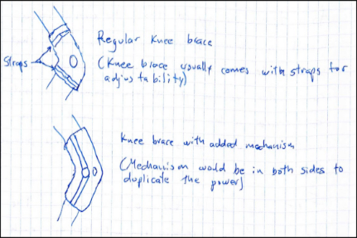
The first part of the device is the knee brace. A knee brace is usually made of textile materials or plastic and wraps around a person’s knee to give support or prevent injuries. Knee braces usually comes in different sizes and is easily adjustable. The function of this part within the design is to provide support like usual, make the device adjustable, and to provide a casing for the mechanism so it won’t be placed directly on the skin, which would cause the user to be uncomfortable.
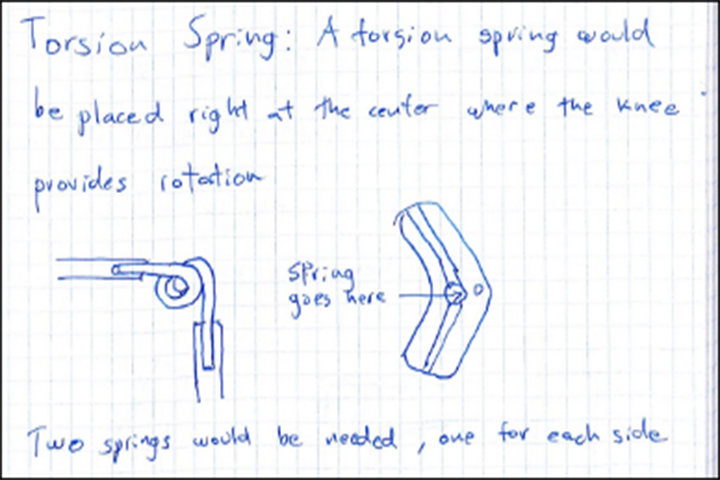
The second part is the mechanism itself. The mechanism is made of two 5 to 10 inch long levers connected by a torsion spring. The torsion spring would be in a 180 degree position at rest, or a calculated resting point depending on the user. Upon torsion acting on the spring, it would rotate to a 90 degree angle or less depending of the range of motion of each user. This would convert the weight of the person into potential energy on the spring. Each knee brace would have a set of springs and levers on each side, making it a total of 4 springs on both legs. The function of this part is to store potential energy and release it into kinetic energy as the person stands up.
The third and last part is the lock and release system. In order for the device to be efficient it has to be able to store the potential energy for as long as the person is seated and to be able to release it on demand as the person stands up. The design will include a mechanism that will lock it in place as soon as the spring reaches its compressed state. The mechanism will only lock the spring, but not the levers thus allowing the user to still move their legs freely while sitting down. Then, when the person wants to stand up they will simply push a button that will release the spring. This mechanism will be able to lock the spring at different angles, this will account for people who can’t achieve a full 90 degree angle with their knees.
Approach to Solution
In order to find the most appropriate solution the team decided brainstorming was the best idea. Each team member had to brainstorm over the period of five days, and come up with three different design solutions to the problem on their own. After every member had the three ideas, the remaining two members had to pick the best option out of a member’s ideas. This means the team conceived a total of nine ideas and then narrowed them down to three main concepts we could compare and contrast.
Idea 1: Spring Loaded Seat
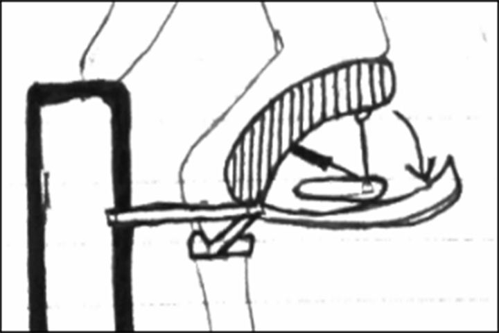
The idea for this device is a seat which can easily be folded up and carried around. It is built with a spring inside that charges up as the user sit down on it. As the occupant sits down, the spring converts their initial potential energy and kinetic energy into charged up kinetic energy for later. Also, the spring acts as a damper on the sitting down motion, reducing the burden of the movement on the user’s knees. The seat is connected by a rod to the knee of the occupant and helps prevent the knee from moving in the wrong direction or blowing out as the occupant sits down and stands up. Also, the device is optionally connected to the user’s walker so that the user can rely on the walker’s assistance to stand before and after they sit. To operate the spring to help the occupant stand, the user will put their hands on their walker and press the operating button on the walker. After the user has stood up and is using the walker for assistance, the device can be collapsed and attached to the walker for mobility.
The side view of the concept can be seen below. As the user sits down, the spring loads up and the cushion locks into the case, creating a seat. The arm connecting to the walker helps ensure that the user can avoid falling. It can be a complete seat, or a seat split down the middle into two separate spring seats, so that it can fit any size person and easily attach to the walker.
Idea 2: Knee Brace with Levers/Spring Mechanism
The idea for this device is to incorporate a lifting mechanism into what is commonly known as a knee brace. This device would have the adjustability and comfort of a regular knee brace, but attached to it would be a mechanism with a torsion spring that would store potential energy as the person sits down. Then, the spring would be locked so the energy can be saved for later use when the person stands. The concept behind this idea is to use metal bars attached to the legs through the knee brace as levers and these levers would be connected to a spring. As soon as the person sits down, the torsion spring compresses and stores potential energy. Upon reaching its maximum bending point the mechanism would theoretically lock in place so the person can move their legs freely without worrying about losing the stored potential energy. Once the person wants to stand up, the user simply puts his legs down and unlocks the system so the spring releases its potential energy into kinetic energy.
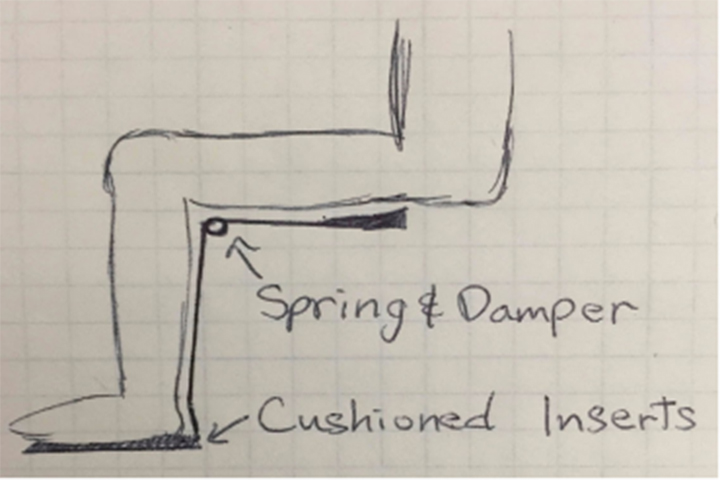
Idea 3: Full Thigh Support
The goal for this device is to help get the initial upward motion out of a chair. As people attempt to get out of the chair, the upper body leans forward to actuate the motion. When this happens, the center of gravity shifts from above the buttocks to the upper thigh. Most of the force/pressure is on the ball of the foot as the body lifts up the buttocks up into a standing position. This device will help imitate that motion so that the user will put less stress onto the knees.
There will be two pads on the upper thighs that are connected to rods on both legs. These rods located below the thighs are connected to rods that run along the calves. The rods along the calves are connected to cushioned shoe insoles, which people can put into their shoes or walk around stand alone. The main component in this device is a spring and damper system fit under the knee that supports the sitting down motion along with helping with stand up without any need of other external devices or people. Once the user wants to stand up, the weight will be sensed by the shoe inserts and actuate the spring section of the device. While standing straight, the device will still be sensing the weight of the user and command the spring to be fully extended which will help support the body.
In order to decide which design was best, the team decided to opt for the weighted decision matrix. To help decide which design to use, the designs were compared based on the characteristics and rated them 1 through 3. The design with the highest score is the device that would be further developed.
| Spring Loaded Seat | Knee Brace With Lever/Spring | Full Thigh Support | Comments | |
|---|---|---|---|---|
| Adjustability (2) | 3 | 3 | 3 | All designs are fairly adjustable and fit most users. |
| Comfort (3) | 2 | 2 | 1 | First design includes a seat cushion. |
| Convenience (3) | 1 | 2 | 2 | First design requires the user to carry the device. |
| Durability (2) | 3 | 2 | 2 | Second design is exposed and therefore vulnerable. |
| Effectiveness (3) | 2 | 2 | 3 | First design requires a walker to be effective. |
| Range of Motion (2) | 2 | 3 | 2 | First design doesn’t provide the full range of motion. |
| Simplicity (1) | 2 | 3 | 1 | Second design is the simplest. |
| Support (2) | 1 | 2 | 3 | First design doesn’t provide support while standing. |
| Total Raw Score | 16 | 19 | 17 | |
| Weighted Score | 35 | 41 | 39 |
From the weighted decision matrix it can be observed that each design had their own strengths and weaknesses. For the first design, the device fits everyone since it ‘s just a seat, but some other factors are limited like support while standing and convenience, since the user had to carry it around and relied on a walker, which not all the intended users would have. The second idea, which had the best score, had a really simple design, was adjustable to any size and had a great range of motion and convenience since the user only had to wear it and not carry it around. The third design was similar to the second design, since it relied on lifting using a junction next to the knee, but since the third design had to be worn all along the legs it was much left comfortable than the other designs.
Aside from the weighted decision matrix, the decision was made on good old instinct. The first design seemed like a hassle to carry around and it relied on a walker or some other source of support to remain stable, so it seemed cumbersome. The third design, even though similar to the second design, seemed really uncomfortable, which would be really unappealing to most people. However, the second design seemed to fit the perfect middle ground between a regular knee brace, which only gives support and a robotic knee which would help the user with the work. The reason a weighted decision matrix was used as the main object of the selection process is due to its ease to use and understand. Someone who has no idea of what the designs are can easily see the matrix and understand it without having any background information.
Design Solution
The selected design was the knee brace with levers and a spring mechanism. The device is meant to support the person while walking, to be comfortable to wear, to be adjustable to different sizes, and mainly to be able to aid the person to stand up. In order to understand the device better it will be broken down into parts and explained on each of the functions.
The first part of the device is the knee brace. A knee brace is usually made of textile materials or plastic and wraps around a person’s knee to give support or prevent injuries. Knee braces usually comes in different sizes and is easily adjustable. The function of this part within the design is to provide support like usual, make the device adjustable, and to provide a casing for the mechanism so it won’t be placed directly on the skin, which would cause the user to be uncomfortable.
The second part is the mechanism itself. The mechanism is made of two 5 to 10 inch long levers connected by a torsion spring. The torsion spring would be in a 180 degree position at rest, or a calculated resting point depending on the user. Upon torsion acting on the spring, it would rotate to a 90 degree angle or less depending of the range of motion of each user. This would convert the weight of the person into potential energy on the spring. Each knee brace would have a set of springs and levers on each side, making it a total of 4 springs on both legs. The function of this part is to store potential energy and release it into kinetic energy as the person stands up.
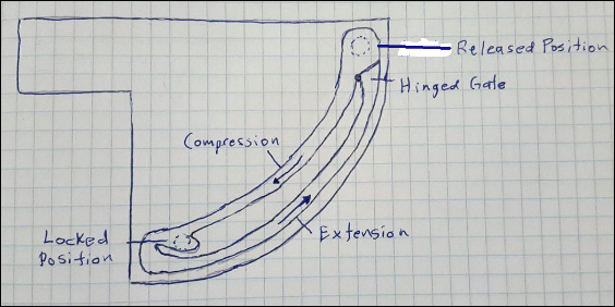
The third and last part of the mechanism is the lock and release system. In order for the device to be efficient, the device must be able to store the potential energy for as long as the person is seated and to be able to release it on demand as the person stands up. The design will include a mechanism that will lock in place as soon as the spring reaches its compressed state. The mechanism will only lock the spring, but not the levers. This will allow the user to still move their legs freely while sitting down. Attached to the end of the spring would be a cylindrical bar perpendicular to the knee. As the spring compresses, the bar travels along the compression path until it reaches the locked position. Once the spring is locked, the user would only need to compress the spring a little further in order to reach the end of the compression path. Then the spring would compress into the extension path, returning all the way into the released position where it started. At the end of the extension path there is a spring loaded hinged gate, so that as soon as the bar reaches the released position, the gate will close again forcing the bar to go through the compression path. Then, when the person wants to stand up they will simply bend their knee a little further before standing up so that the spring can be released. This mechanism will be able to lock the spring at different angles, which will account for people who can’t achieve a full 90 degree angle with their knees.
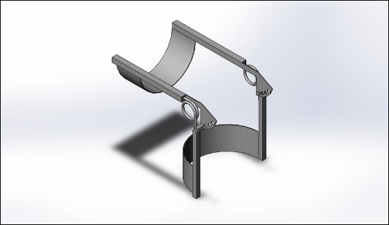
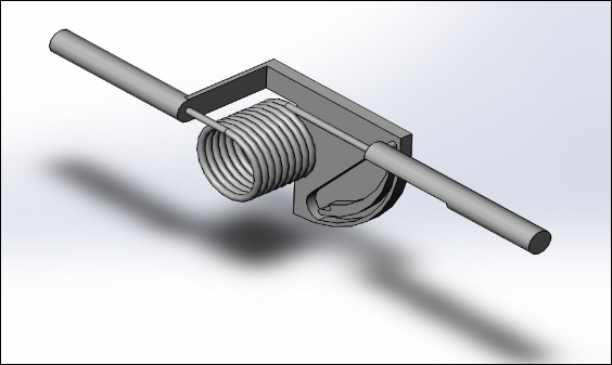
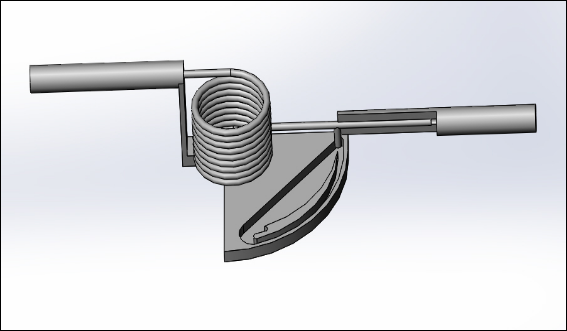
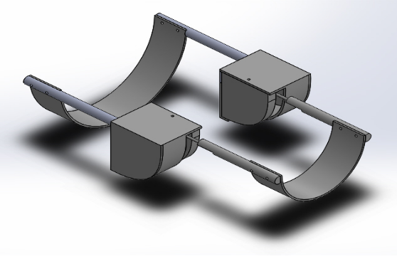
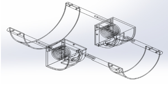
It is difficult to include the sleeve in the rendering, so the 3-Dimensional representation is only of the metal components of the design. Also, the design is constantly changing to improve and work towards a finalized design before the manufacturing process begins.
Modeling and Analysis
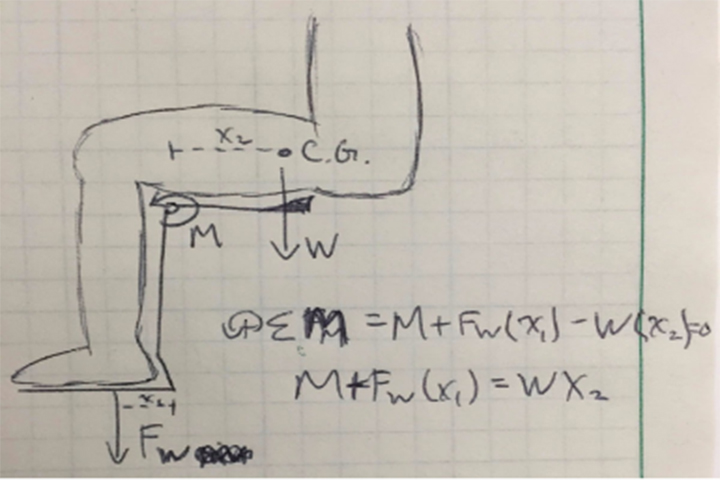
The knee brace mechanism is designed to utilize torsional springs to store potential energy provided by the user and minimize the shock onto the knees when the user stands up and sits down respectively. A secondary function of the knee brace mechanism would be to support the user while they are walking by providing a small spring loaded momentum during the heel strike stage of walking. The spring constant needed to help the user get out of a chair can be found by calculating the torque the knee needs to produce. This torque can also be calculated by modeling the device as a torsional spring-mass system and analyzing it with the provided specifications of the user such as: height, weight, the angle of the upper body makes with the thigh, and the angle the calf makes with the thigh. The actual values will differ based on the user’s weight and height, therefore the modeling and analysis was calculated with an average weight and height in mind.
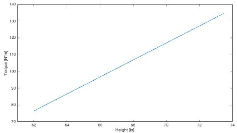
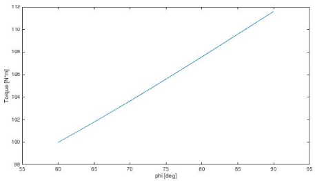
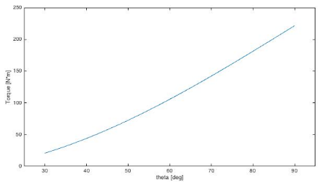
Due to the amount of variables within the system, torque is a function of height, weight, the angle of the upper body makes with the thigh (θ), and the angle the calf makes with the thigh (φ). The importance of a variable can be found by varying one variable and keeping the rest at a set value, this was done for the four variables, see Appendices 1-4. As seen in Appendix 3, the angle of the calf does not affect torque as much as the other variables. The difference in maximum and minimum values are around 12 N•m when the difference for other variables are above 50 N•m.
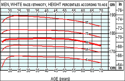
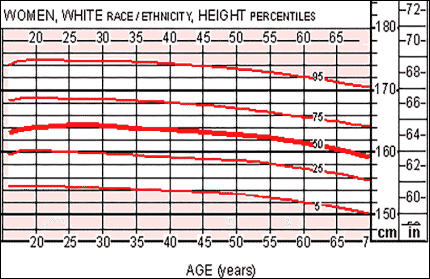
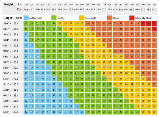
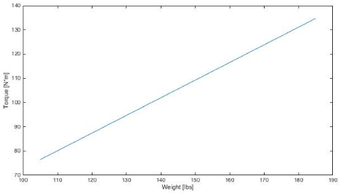
There is another correlation between the height of the person and their weight. This is used to estimate the weight range of customer which is later used to calculate which spring to use in the model. Assuming the customer is in the healthy regime, the minimum and maximum range for women and men are [105-165] and [125-185] pounds respectively. When looking at both sexes as a single group, the weight range that the mechanism must support is between [105-185] pounds.
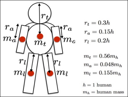
Since the user is not lifting their total body weight, body ratio assumptions were made to calculate how much the knee has to lift. Assuming that the thigh is ⅔ of the weight of the leg, we can calculate the amount of weight the knee must lift. The head weight is 0.034 • mh. This means that the weight that the knee must lift is (0.034 + 0.56 + 2 • 0.048 + 2 • 0.155 • ⅔)mh = 0.8967 • mh = [94.15 - 165.8833] lbs or [42.7057 - 75.2434] kg.
Due to the amount of variables within the system, torque is a function of height, weight, the angle of the upper body makes with the thigh (θ), and the angle the calf makes with the thigh (φ). The importance of a variable can be found by varying one variable and keeping the rest at a set value, this was done for the four variables. The angle of the calf does not affect torque as much as the other variables. The difference in maximum and minimum values are around 12 N•m when the difference for other variables are above 50 N•m.
Prototype Plan
The purpose of the prototype is to verify that the design works and accomplishes the desired task of lowering the burden on the knees when sitting and standing up. The first plan of action will be modeling the design virtually in Solidworks. By modeling it in Solidworks, any problems be identified in the initial design and easily adjusted to produce the desired outcomes. The Solidworks design will be the essence of the design, i.e., the raw idea, rather than a highly detailed and complete one. The design in Solidworks can be used to verify where the prototype experienced the most stress and strain. Once this is know, adjustments can be made reinforce these areas and guarantee a safer product.
Once the design is rapidly prototyped virtually, the next plan of action will be to assemble a physical prototype. With the physical device, adjustments will be custom tailored for comfort, by adding cushion and padding. Test trials will be conducted by the developers and adjustments will be made accordingly. Also, there is a possibility that the prototype could break and a second prototype will have to be made. In order to avoid reconstructing the prototype again, tests are made by modeling it virtually in advance and calculating where the device might fail or break before the actual build of the physical prototype is initiated.
With a working, comfortable and safe device in hand, the device will be presented to the target market and record their feedback after testing the device. Our friends and or family with knee ailments will also provide detailed feedback. If enough time is provided, feedback will be incorporated into the final device and if there is not enough time, the feedback will at least be included in the final presentation as notes to move forward.
Virtual Prototype or Simulation
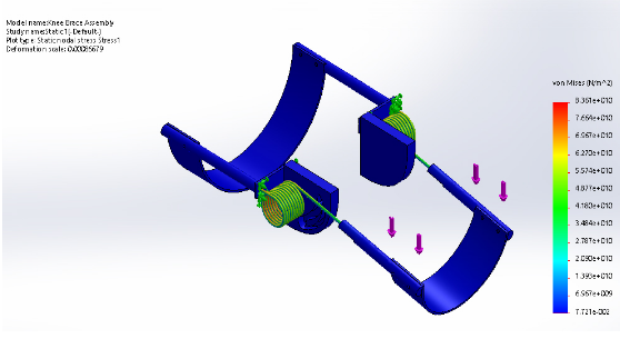
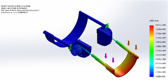
For the virtual prototype and simulation, Solidworks is used to view the section needs the most support. There will also be a Matlab code that will calculate the amount of torque needed to lift the person, which helps in picking the correct spring for the person. The simulation will be processed by anchoring one side of the legs while adding weight to the tip of the other leg attached to the spring. This process will be done for different weights to analyze which point is under the most stress. Adjustments will be manufactured if any part of the mechanism is under extreme stress or fractures. The goal would be for the mechanism to withstand a compressive force for the weight of 170 pounds. After each simulation, the virtual prototype will be displayed with different colors at different sections to display the points with the highest stress. Using these values, a graph of stress vs weight can be produced. This way, we can see how weight is correlated to the amount of stress onto the mechanism. This process can be done multiple times after modifications are conducted to minimize the amount of stress.
Physical Prototype Construction Detail
When the complete model is finished on Solidworks, the construction details of the prototype will be updated in the future. For now, the following is the bill of materials:
| Material | Vendor | Quantity | Price Per Item | Total |
|---|---|---|---|---|
| 72in Aluminum Round Rod (0.5 diameter) | MSC Industrial Supply | 1 | $14.48 | $14.48 |
| Knee Sleeve | Amazon | 2 | $10.00 | $20.00 |
| 180° Torsional Spring | McMaster | 4 | $6.89 | $27.56 |
| 8x8in Aluminum Plate | MSC Industrial Supply | 1 | $20.12 | $20.12 |
| Miscellaneous Parts (straps, screw, etc.) | Amazon | N/A | N/A | $30.00 |
| Total Cost | $112.16 |
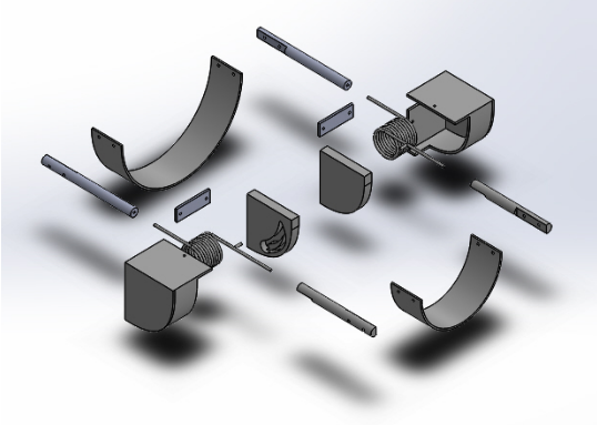
The design includes two spring mechanisms in each leg, one on each side, so the total number of spring mechanisms that will be built is four; two left on the left side and two on the right side. They will use the same materials but will be mirrored to be easily placed on each side. The aluminum round rod is meant for the levers that are attached to the spring mechanism and run along the user’s legs, these rods will also be attached to the knee sleeve. Since two bars are needed for each spring mechanism, the total number of bars used is eight. Assuming the bars will be between five to eight inches each, the total amount needed is between 40 and 64 inches of aluminum rod. The knee sleeve is what will be holding the spring mechanism and are also meant for comfort. The torsional springs are the key component of the mechanism, for the dimensions and price we assumed we are using the spring with the highest torque. The aluminum plate is meant for the lock system that houses the spring mechanism. Finally, an assumption is made as there are some parts that are not yet taken into account, since the design may change or simply the parts are not taken into account yet, like the straps between the bars and the knee sleeve.
Description of Prototype
The prototype is similar to the initial design except for the fact that it lacks all aesthetic and comfort characteristics, such as padding on sections that are in contact with the body. Once the assembly of the prototype is completed and the core design undergoes small adjustments to fulfill the design criteria and to check its conceptual functionality, the other characteristics will be added onto the design. Each side of the prototype is comprised of the following: a base plate produced by the CNC machine, an aluminum torsional spring, attaching aluminum rods, connecting bands made from sheets of aluminum, and a plastic cover for the mechanism that was 3D printed at the Orbach Science Library. All aluminum parts were purchased from I.M.S. and the spring was from McMaster. These pieces were machined at the UCR Machine Lab using the mill and lathe machine. The main purpose for the prototype is to check if the proposed function works.
The spring mechanism is the main component of the design. It is all housed in a neat 90° circular wedge. The bottom of the spring mechanism unit is comprised of the base plate which contains the track for the spring follower member to slide on and lock when fully compressed. The top cover of the wedge is the housing unit, which was printed by a 3D printer at the Orbach Science Library. This cover for the housing unit keeps the calf end of the spring within its track of motion and the thigh end fixed. It also prevents any distortion, damage, or weather erosion from outside contact and discomfort to the user.
The spring housing mechanism is connected to the rest of the brace through connecting machined aluminum rods. These rods are both six inches long with a half inch diameter and will be attached to both sides of the leg: the calf and the thigh. The thigh connecting rods were lathed to hold the springs ends and do not move as the user gets up and down. Once the holes were drilled using the lathe, the mill was used to produce a flat surface and drill holes to attach the sheet metal which would act as the strap underneath the thigh. Once the holes were drilled all the way through, a #6-32 tap was used in order to produce threads within the rods. The calf connecting rods loosely hold the spring ends as they were lathed and then milled halfway through, which give an opening for the spring ends to detach. These rods also had holes drilled on the polar end and threaded with the same #6-32 tap. This is where the connecting aluminum bands, of which there are only two in total, connect the mirrored sides of the brace. The thigh band is slightly longer than the calf band to accommodate the housing unit.
Evaluation Method
Once the prototype is complete, it will go through multiple tests to ensure that the device operates as desired. To evaluate the physical prototype, photos will be taken and stop motion video will be used as the user sits up and down. We will first record ourselves sitting up and sitting down without the device five times to get a baseline for speed and process. Then we will equip the knee brace and attempt to do the same as before. By examining the rotational speed of the mechanism we can evaluate the compression of the spring and the resistive force it is providing. We will also take this opportunity to evaluate if the spring constants of our torsional springs match what the manufacturer claimed. Since the spring operates based on the relationship, and each spring must carry the load of a quarter of the user’s weight, each spring must take less than a fourth of the user’s weight to compress or the device will not allow the user to sit down. We will utilize force springs to test exactly how much force needs to be applied to fully compress the spring when the static side is anchored down.
At this point, the physical prototype was not completed, therefore we utilized Solidworks to evaluate the prototype. We applied numerous forces to the mechanism to see the motion of the device, where points of stress were and any issues with our design.
Test Results
After performing the stress analysis on Solidworks, the results came to display that the majority of the stress falls upon the springs. We predicted this would happen, thus we utilized relatively resilient springs. The Solidworks analysis indicates that the springs will not fracture under the force of the user’s weight as they sit down. The prototype operated as desired when force was applied on the calf band in Solidworks. One thing that was not accounted for was the change in material property when the guide piece was welded onto the spring. The high heat exposed onto the spring caused the spring to change material properties into a brittle nature. Due to the change, the guide snapped off at the location of welding.
Evaluation of Design Performance vs Design Requirements
During the design process, the goal was to have the following features incorporated: hands free and self powered device, a lock and release system, a spring loaded knee support, and a customizable brace that can fit a variety of knee sizes and ranges of motion. The device contains all the the desired features. It does not require any electronics or manual operation to function, thus fulfilling the desire to be hands free. All the user has to do to make the device function is sit down when they want to redistribute the load of sitting down, and lean forward slightly before standing up to utilize the stored energy of the spring when standing. With the ability to switch spring constants by using different metals, and the ability to elongate the length of the connecting bands, the device is highly customizable.
Considering the results of the Solidworks force analysis we believe that the device will handle the pressure from the user’s weight with ease and help that user sit down while exerting less force on their knees. We still have to make sure that the physical prototype operates identically to the virtual one tested in Solidworks. After the first two tests with the physical prototype, there was a significant difference between using the device and without the device. However, after the two tests the guide on the spring snapped off due to the changed brittle nature.
Recommendations of Design Improvements and/or Implementations
To improve this design, the device should become lighter and sturdier materials should be used. While aluminum was a great material for a prototype, it would not be ideal to use for the actual mechanism. A better choice would have been something that was lighter while not comprising on strength. It is also believed possible to reduce the bulkiness and sheer size of the spring mechanism. With a simpler and more compact approach it is possible to bring down the size and overall weight of the mechanism.
It is absolutely essential that this device be padded and comfortable for the user. The main goal for the device is supposed to provide support, not pain. This would be done by using thick padding on the bottom plate of the spring mechanism housing unit and a soft fabric covering everywhere where the brace might contact the user’s skin. Thick spandex similar to that used to make compression shorts would be best as it is firm yet comfortable. The plan is to modify the padding to the specifications of someone who actually suffers from knee problems.
Conclusion
The prototype design achieved everything set out to achieve. It reduces the load on the knees by carrying some of the load through the spring resistance. It also does this without the need for manual operation or external support. The testing proved that the hypothesis was successful, however the service life of our physical prototype was too short for our liking. There are many things which would have been changed for the second prototype, unfortunately there was not enough time to produce a second prototype.
Read the Final Report:
HERE
References
[1] “Stanford Center On Longevity Design Challenge”, Stanford Center on Longevity Design Challenge 2015-2016. n.p., n.d. Web 5 Oct. 2015.
<http://longevity3.stanford.edu/designchallenge2015-16/>
[2] “What is Arthritis?”, Arthritis Foundation. n.p., n.d. Web 27 Oct. 2015
<http://www.arthritis.org/about-arthritis/understanding-arthritis/what-is-arthritis.php>
[3] “Osteoarthritis”, National Institute of Arthritis and Musculoskeletal and Sin Diseases. n.p., n.d. Web 27 Oct. 2015
<http://www.naims.nih.gov/Health_Info/Osteoarthritis/default.asp>
[4] “Harvard University School of Public Health - Staying Active”, The Nutrition Source. n.p., n.d. Web 27 Oct. 2015
<http://www.hsph.harvard.edu/nutritionsource/staying-active/>
[5] “Midwest Orthopedics at RUSH”, Sports Medicine - Knee Injuries. n.p., n.d. Web 27 Oct. 2015
<http://www.rushortho.com/sm_knee_injuries.cfm>
Appendices
Equation 1: Force = ((Degrees of Rotation°)(Kspring))/(Moment Arm)
Matlab Code:
%%Finding Input Values
%Finding Weight and Height
prompt1 = 'What is Weight of Person?[lbs]';
W = input(prompt1)*0.453592*9.81;  %[N]
Fb = (0.034 + 0.56 + 0.048*2) * W;
Ft = (0.155*2*2/3) * W;
Ff = (0.155*2*1/3) * W;
prompt2 = 'What is the Height of Person?[in]';
H = input(prompt2)*0.0254;  %[m]
x1 = 0.55 * H * 0.55;
x2 = 0.5 * 0.45 * H * 2/3;
x3 = 0.5 * 0.45 * H;

%Looking at Angles
prompt3 = 'What is Leaning Angle?';
theta = input(prompt3);
prompt4 = 'What is Leg Bending Angle?';
phi = input(prompt4);

%%Calculation
M = Fb*(x2-x1*cosd(theta))+Ft*(2/3*x2)-Ff*(x3*cosd(phi))

%%Plots
%Theta
figure
H = 67.75*0.0254;          %[m]
x1 = 0.55 * H * 0.55;
x2 = 0.55 * 0.45 * H;
x3 = 0.45 * 0.45 * H;
W = 145*0.453592*9.81;     %[N]
Fb = (0.034 + 0.56 + 0.048*2) * W;
Ft = (0.155*2*2/3) * W;
Ff = (0.155*2*1/3) * W;
phi = 75;
theta = linspace(30,90);
M1 = Fb*(x2-x1*cosd(theta))+Ft*(2/3*x2)-Ff*(x3*cosd(phi));
plot(theta,M1)
xlabel('theta [deg]');
ylabel('Torque [N*m]');
xlim([25,95]);

%phi
figure;
H = 67.75*0.0254;          %[m]
x1 = 0.55 * H * 0.55;
x2 = 0.55 * 0.45 * H;
x3 = 0.45 * 0.45 * H;
W = 145*0.453592*9.81;     %[N]
Fb = (0.034 + 0.56 + 0.048*2) * W;
Ft = (0.155*2*2/3) * W;
Ff = (0.155*2*1/3) * W;
theta = 60;
phi = linspace(60,90);
M2 = Fb*(x2-x1*cosd(theta))+Ft*(2/3*x2)-Ff*(x3*cosd(phi));
plot(phi,M2)
xlabel('phi [deg]');
ylabel('Torque [N*m]');
xlim([55,95]);
%Weight
figure;
H = 67.75*0.0254;          %[m]
x1 = 0.55 * H * 0.55;
x2 = 0.55 * 0.45 * H;
x3 = 0.45 * 0.45 * H;
theta = 60;
phi = 75;
W1 = linspace(105,185);
W2 = linspace(105*0.453592*9.81,185*0.453592*9.81);
Fb = (0.034 + 0.56 + 0.048*2) * W2;
Ft = (0.155*2*2/3) * W2;
Ff = (0.155*2*1/3) * W2;
M3 = Fb*(x2-x1*cosd(theta))+Ft*(2/3*x2)-Ff*(x3*cosd(phi));
plot(W1,M3)
xlabel('Weight [lbs]');
ylabel('Torque [N*m]');

%Height
figure;
W = 145*0.453592*9.81;     %[N]
Fb = (0.034 + 0.56 + 0.048*2) * W;
Ft = (0.155*2*2/3) * W;
Ff = (0.155*2*1/3) * W;
theta = 60;
phi = 75;
H1 = linspace(62,73.5);
H2 = linspace(62*0.0254,73.5*0.0254);
x1 = 0.55 * H2 * 0.55;
x2 = 0.55 * 0.45 * H2;
x3 = 0.45 * 0.45 * H2;
M4 = Fb*(x2-x1*cosd(theta))+Ft*(2/3*x2)-Ff*(x3*cosd(phi));
plot(H1,M3)
xlabel('Height [in]');
ylabel('Torque [N*m]');
xlim([61,74]);
Matlab code used to calculate the torque using the 4 different variables: weight, height, phi and theta.