Machine Design: Straw Truss Bridge
Objectives
Design and construct a truss bridge within constraints outlined in Specifications. Requirements for the project:
- Agreement between predicted & measured failure loads for constructed bridge
- Measured structural efficiency of the constructed bridge
Specifications
Bridge will be constructed using a total of 25 plastic drinking straws. Specifications and constraints will be as follows:
- Design:
- 12 inch span and 2 inch max width
- Loading apparatus will provide 1 inch wide abutments on either side of span for bridge to rest upon
- Must be self-standing and function without attachment to loading apparatus
- Must accommodate loading at mid-span. Weights will be loaded using 3/16 inch x 2.5 inch, transversely-oriented rod. Wires attached to rod ends will connect to hanging weight beneath bridge.
- No portion of the bridge may extend beneath plane defined by upper abutment surfaces.
- Bridges must be trusses, not simple beams based on bundled straws
- Straws can be cut to desired length, but may not be slit open to form webbing or gusseting
- Construction:
- Use of any other materials is not permitted; nor are pins, tape, gussets, or other means of joining/support
- Strongly encouraged to reinforce area around mid-span loading point to ensure that local deformation does not compromise bridge load-bearing performance unduly
Group Members: David Chon, Andrew Chow, Clayton Chow, Jeffrey Chung, Alexander Decker
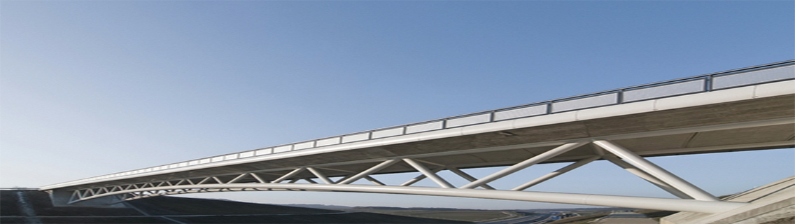
The first plan was to come to a consensus on which type of bridge to create. Most of the members had a good understanding of the different types of truss bridges: Warren, Pratt, Howe and K Truss bridge and each type had legitimate advantages to be chosen over the other. After further research online, the group came to an agreement on building the Warren bridge with a slight modification; by adding a support beam in the dead center.
Estimated Loads
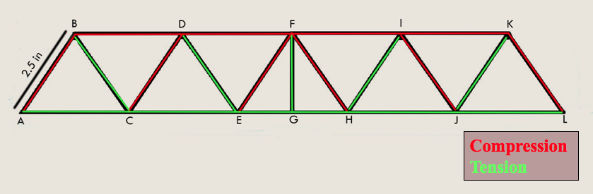
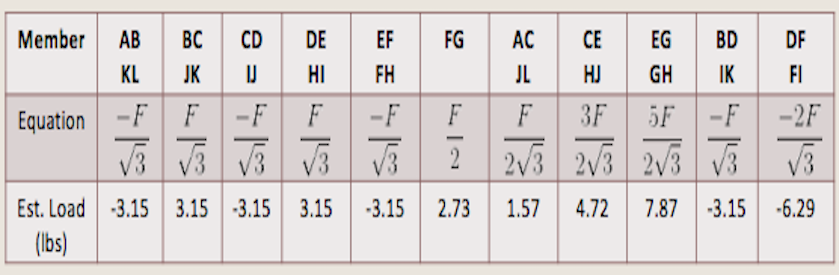
The rough estimations were calculated by knowing the location of force applied, thickness of the material used, length of each section, and the type of support on the ends of the bridge (pinned). The UTS (Ultimate Tensile Strength) and Young’s Modulus were obtained online while the inner and outer diameter were obtained by taking the average of ten readings using an electric caliper. Using the collected data, it was possible to calculate the minimum and maximum critical load.
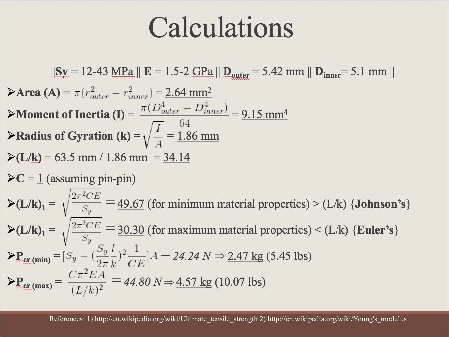
The predicted failure mode would be in-plane buckling and the predicted failure load would be a range of 5.45 - 10.07 lbs. Although we predicted the load can hold double the minimum critical load, it is always best to state the lower limit as the final critical load. Therefore, the predicted load would be 5.45 lbs. The measured failure load turned out to be 9.5 lbs due to in-plane buckling which resulted in a 74.3% error. Although this value is high, it is still within our predicted load range. If this were a real life scenario and stated the predicted was 10 lbs, there could have been an accident on the bridge. Thus, it is always important to use the lower limit when choosing the minimum critical value.