Kinematic and Dynamic Analysis of Mechanisms
Four-Bar Linkage
“A four-bar linkage is the simplest movable closed chain linkage. It consists of four bodies,called bars or links, connected in a loop by four joints. Generally, the joints are configured so the links move in parallel planes, and the assembly is called a planar four-bar linkage.
Planar quadrilateral linkage, RRRR or 4R linkages have four rotating joints. One link of the chain is usually fixed, and is called the ground link, fixed link, or the frame. The two links connected to the frame are called the grounded links and are generally the input and output links of the system, sometimes called the input link and output link. The last link is the floating link, which is also called a coupler or connecting rod because it connects an input to the output.
Assuming the frame is horizontal there are four possibilities for the input and output links:
- A crank: can rotate a full 360 degrees
- A rocker: can rotate through a limited range of angles which does not include 0° or 180°
- A 0-roker: can rotate through a limited range of angles which includes 0° but not 180°
- A π-rocker: can rotate through a limited range of angles which includes 180° but not 0°
Grashof Condition
The Grashof condition for a four-bar linkage states: If the sum of the shortest and longest link of a planar quadrilateral linkage is less than or equal to the sum of the remaining two links, then the shortest link can rotate fully with respect to a neighboring link. In other words, the condition is satisfied if S+L ≤ P+Q where S is the shortest link, L is the longest, and P and Q are the other links.” 1
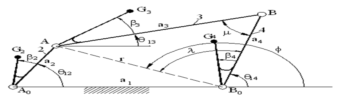
Let a, b, g, and h denote the lengths of the input crank, the output crank, the ground link, and floating link, respectively.
T1 = g + h - a - b, T2 = b + g - a - h, T3 = b + h - a - g.
| T1 | T2 | T3 | Input α | Output β |
|---|---|---|---|---|
| + | + | + | crank | rocker |
| 0 | + | + | crank | π-rocker |
| - | + | + | π-rocker | π-rocker |
| + | 0 | + | crank | 0-rocker |
| 0 | 0 | + | crank | crank |
| - | 0 | + | crank | crank |
| + | - | + | π-rocker | 0-rocker |
| 0 | - | + | crank | crank |
| - | - | + | crank | crank |
| + | + | 0 | crank | π-rocker |
| 0 | + | 0 | crank | π-rocker |
| - | + | 0 | π-rocker | π-rocker |
| + | 0 | 0 | crank | crank |
| 0 | 0 | 0 | crank | crank |
| - | 0 | 0 | crank | crank |
| + | - | 0 | π-rocker | crank |
| 0 | - | 0 | crank | crank |
| - | - | 0 | crank | crank |
| + | + | - | 0-rocker | π-rocker |
| 0 | + | - | 0-rocker | π-rocker |
| - | + | - | rocker | rocker |
| + | 0 | - | 0-rocker | crank |
| 0 | 0 | - | 0-rocker | crank |
| - | 0 | - | 0-rocker | 0-rocker |
| + | - | - | rocker | crank |
| 0 | - | - | 0-rocker | crank |
| - | - | - | 0-rocker | 0-rocker |
Crank-Rocker
S+L < P+Q
(continuous motion)
Parallelogram Linkage
S+L = P+Q
(continuous motion)
Crank Slider (Single Cylinder Engine)
“A slider-crank linkage is a four-bar linkage with three revolute joints and one prismatic, or sliding, joint. The rotation of the crank drives the linear movement of the slider, or the expansion of gases against a sliding piston in a cylinder can drive the rotation of the crank.
There are two types of slider-cranks: in-line and offset.
- In-line: An in-line slider-crank has its slider positioned so the line of travel of the hinged joint of the slider passes through the base joint of the crank. This creates a symmetric slider movement back and forth as the crank rotates.
- Offset: If the line of travel of the hinged joint of the slider does not pass through the base pivot of the crank, the slider movement is not symmetric. It moves faster in one direction than the other. This is called a quick-return mechanism.
An in-line crank slider is orientated in a way in which the pivot point of the crank is coincident with the axis of the linear movement. The follower arm, which is the link that connects the crank arm to the slider, connects to a pin in the center of sliding object. This pin is considered to be on the linear movement axis. Therefore, to be considered an in-line crank slider, the pivot point of the crank arm mus be in-line with this pin point.” 2
Consider the slider crank mechanism as a 2 bar linkage mechanism. The crank with a length, r, and the slider with a length, l.
angles = input('[Position, Velocity, Acceleration]= ');
r1 = input('Crank Length= ');
r2 = input('Slider Length= ');
piston = input('Slider Dimensions [height width]= ')
theta = angles(1);
while theta <= 360
	alpha = asind(r1 • sind(theta)/r2);
	x0 = 0;
	y0 = 0;
	x1 = r1 • cosd(theta);
	y1 = r1 • sind(theta);
	x2 = x1 + r2 • cosd(alpha);
	y2 = 0;
	sx1 = x2 - piston(2)/2;
	sx2 = x2 + piston(2)/2;
	sy1 = y2 + piston(1)/2;
	sy2 = y2 - piston(1)/2;
	axis ([-r1-1 r1+r2+piston(2)/2+1 -r1-1 r1+r2+1]);
	axis square;
	hold on;
	plot([x0 x1 x2],[y0 y1 y2],'k','LineWidth',2);
	plot([sx1 sx2 sx2 sx1 sx1],[sy1 sy1 sy2 sy2 sy1],'g','LineWidth',2)
	P0_Circle = viscircles([0 0],r1,'LineStyle','--');
	P1_Circle = viscircles([x0 y0],0.1);
	P2_Circle = viscircles([x1 y1],0.1);
	P3_Circle = viscircles([x2 y2],0.1);
	pause(0.001);
	clf;
	theta = theta + angles(2) • (180/pi)/60;
	if theta > 360
		theta = 0;
	end
end
angles = [0 3 1]; r1 = 2; r2 = 5; slider = [2 4]; theta = angles(1);